This is an old revision of the document!
Table of Contents
Virtual Provide Edge
— Palani Chinnakannan 2014/11/10 20:31
Introduction
A virtual provider edge (vPE) is a virtual network function that provides the traditional provider edge functionality in the virtual environment. This project provides the testing methodology and test cases for integration testing of the OPNFV platform to host a generic VNF like vPE and measure the performance characteristics associated with the vPE traffic patterns. This project uses a L3VPN connectivity over a MPLS backbone network to provide private and secure communication to all devices belonging to a tenant located at multiple sites. The document covers the following elements:
- vPE Topology
- High level Software Architecture
- Hardware Requirements
- Software Components and Requirements
- NFVI Platform Function Test Cases
- Platform Performance Test cases
vPE Topology
The Basic vPE topology comprises of a single instance virtualized provider edge (vPE VNF) that provides L3VPN based connectivity between all sites of a given tenant. Advanced configuration comprises of three or more vPE VNFs providing connectivity to multiple sites belonging to a customer, with the sites distributed between the vPE VNFs. In both cases, multiple tenants are emulated each with 4 or more sites to provide a realistic traffic pattern to stress the NFVI infrastructure through the vPE VNFs. In the basic case, the vPE VNF is hosted on a single server, while in the advanced case, the vPE VNFs are tested on multiple servers, The environment also provides the traffic flow between the CE devices belonging to a tenant.
Basic vPE Topology
The following figure provides the basic topology for the vPE use case functional and performance testing.
The following are the salient aspect of this figure:
- The SUT (system under test) is the OPNFV platform as well as some elements of the VNF (vPE) like the QEMU, virtio etc., that are outside the bounds of the guest kernel, providing the interface to the VNF.
- A single instance of a open source or vendor provide vPE is instantiated on the OPNFV platform.
- The logical topology comprises of 4 tenants name VPN1 through VPN4. Each tenant owns four VPN sites, two directly connected to the VNF under test (VPNx-1, VPNx-2 and two connected to a emulated PE router VPNx-3, VPNx-4). This provides enough routes to stress the vPE VNF instance, which in turn stresses the OPNFV platform.
- The logical topology of CE/PE devices are emulated using IXIA device with two ports allocated for one instance of this topology. The tests performed creates multiple instances of this topology for reliability testing and therefore the test requires 8 to 16 IXIA ports.
| Entity | V4 Address | V6 Address | VLAN | AS Number | RD | VRF Name | RT | Advt Prefixes | Members |
|---|---|---|---|---|---|---|---|---|---|
| CE-1-1 | 15.1.1.1 | 101 | 101 | 65001 | vrf-CE-1-1 | 65001:101 | 14.1.1.0/24 thru 14.1.254.0/25 | CE-1-2, CE-1-3, CE-1-4 | |
| CE-1-2 | 15.1.2.1 | 102 | 102 | 65002 | vrf-CE-1-2 | 65002:102 | 14.2.1.0/24 thru 14.2.254.0/25 | CE-1-1, CE-1-3, CE-1-4 | |
| CE-1-3 | 15.1.3.1 | 103 | 103 | 65003 | vrf-CE-1-3 | 65003:103 | 14.3.1.0/24 thru 14.3.254.0/25 | CE-1-1, CE-1-2, CE-1-4 | |
| CE-1-4 | 15.1.4.1 | 104 | 104 | 65004 | vrf-CE-1-4 | 65004:104 | 14.4.1.0/24 thru 14.4.254.0/25 | CE-1-1, CE-1-2, CE-1-3 |
Advanced vPE Topology
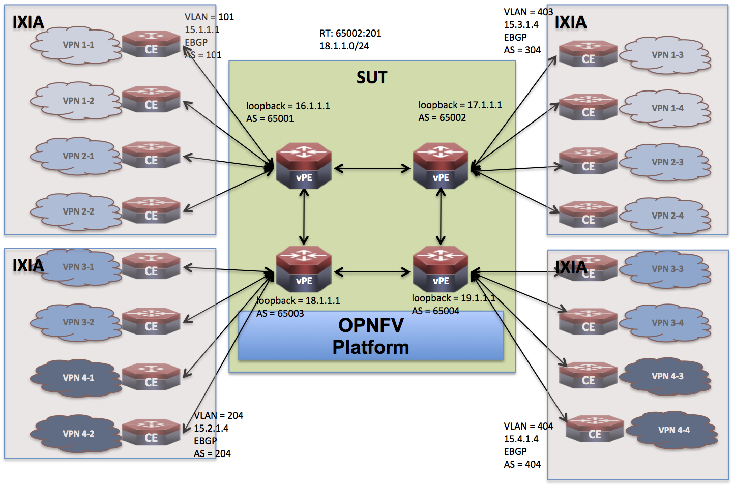
The following figure provides the advanced topology for the vPE use case functional and performance testing.
 The following are the salient aspects of the above topology:
- The topology consists of four vPE VNFs that are instantiated on the SUT. The test cases identified later specifies how the four instances are deployed. For example, one the same physical server or spread across 4 servers.
- The CE devices (emulated) are distributed across the four instances.
- The focus of this topology is to study the behavior of the OPNFV platform under multiple VNF deployments.

