This page discusses the VSPERF Test methodology in detail.
WORK IN PROGRESS - DO NOT PANIC UNTIL INSTRUCTED TO DO SO BY THE CAPTAIN OR A MEMBER OF THE CREW
Test Specification Overview
This section provides detailed information on the test specification and approach that is not covered in the test specification itself.
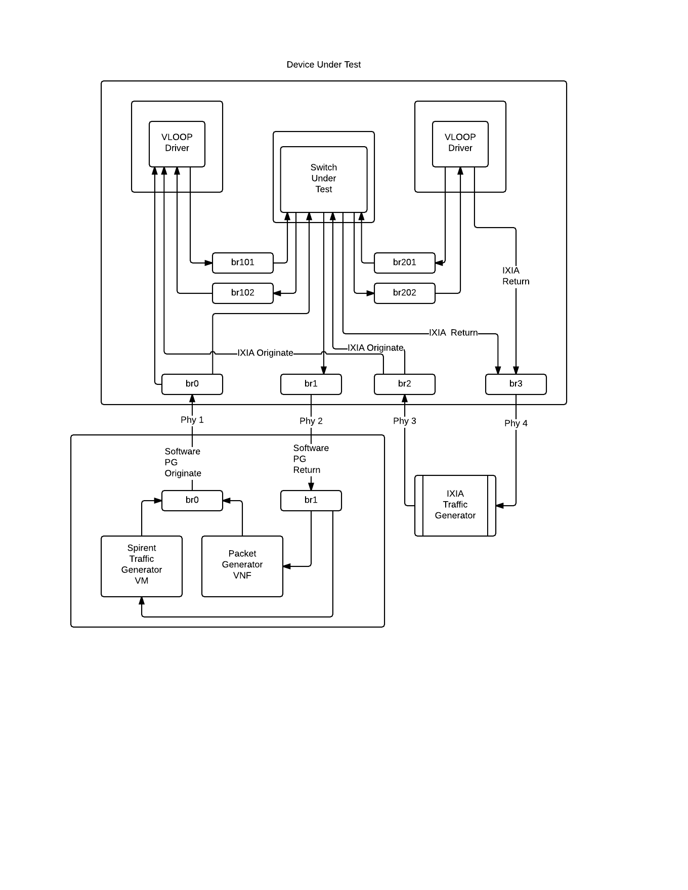
Test Topologies
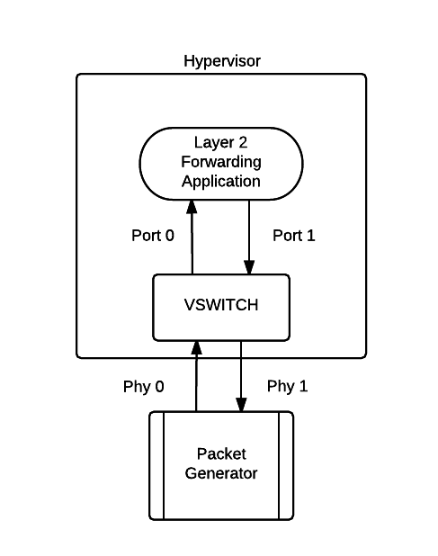 | 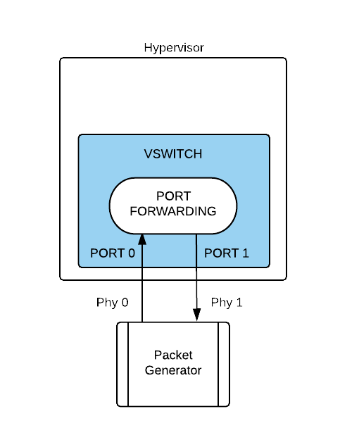 | 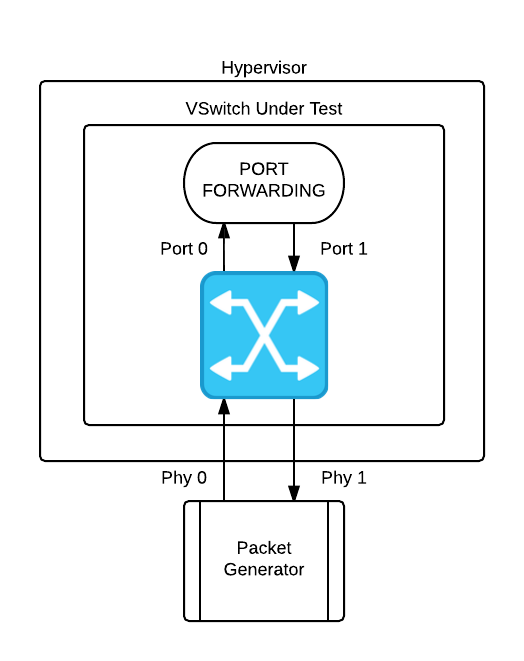 | 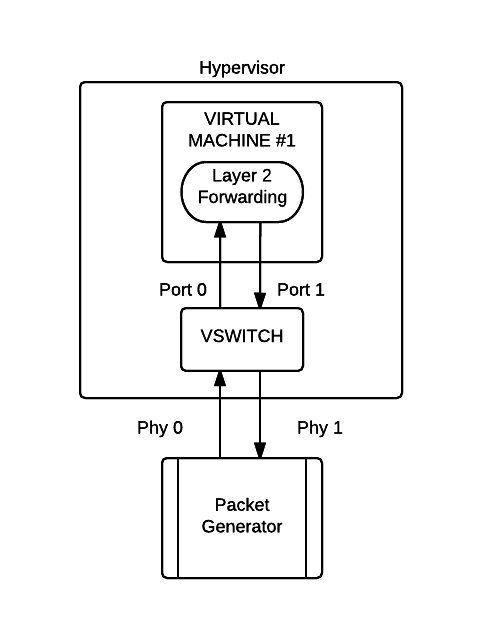 |  |  |  |
NOTE: Use this tool to update these drawings above: https://www.lucidchart.com/community?q=opnfv
TOIT High Level Design
This section provides information about the TOIT framework high level design.
Test Automation with VSPERF
This section provides information about automating the TOIT framework using Jenkins.
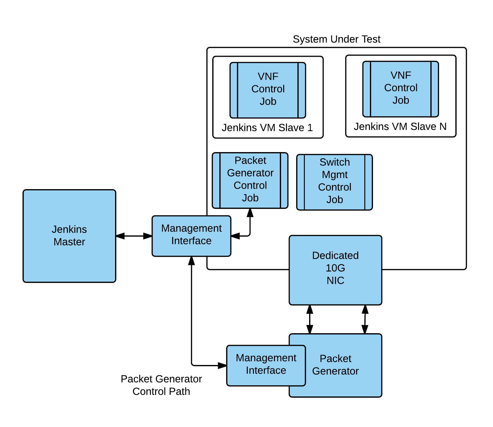
The Continuous Integration Process for VSPERF is built on the TOIT framework based on the Jenkins automation tool. Many of the process control technologies used by TOIT are migrated to Jenkins with each of the major functions delegated to a Jenkins job and much of the runtime configuration provided by variables passed to the job by Jenkins.
Each run has the concept of a primary job, this uses the Jenkins Rest API to manage other jobs that provide services. Each configured hypervisor has the concept of a sibling hypervisor which is connected to a hardware packet generator or configured with physical NICs logically connected ‘back to back’
This diagram illustrates the DUT Virtual Topology
Let’s consider the simplest possible example, Point to Point loopback with OVS and the 2544 data set. This will use 4 Jenkins jobs.
- The VSPERF P2P management job – The driving job for this test. This job normally runs on Jenkins master
- The VSPERF build job – This job compiles the VSPERF tree and assembles any artifacts such as packages, drivers to make them available for downstream jobs. The ‘checkinstall’ tool is used to capture any ‘make install’ operations
- The P2P Switch job is responsible for switch configuration and execution management
- The Packet Generator VNF Job – Responsible for providing packet generation service
- The Reporting Job – Responsible for process test artifacts to produce a results document
Now let’s take a look at the workflow. The VSPERF P2P job first launches the build job and monitors its progress using the Jenkins REST API. This job is the same for all VSPERF automation. Once the build has completely successfully the artifacts are archived and the build job exits.
Once the P2P job detects that the build has completed successfully it then launches the P2P Switch job where the real work is done. Based on the build parameters the P2P Switch job first installs the switch under test and does any preliminary configuration. Once the switch is configured the P2P Switch uses the Jenkins REST API to launch the Packet Generator VNF job in a virtual machine on its ‘sibling’ hypervisor by passing this ‘Node’ parameter to the PGVNF job.
Based on the ‘Node’ parameter Jenkins will launch the PG VNF on the sibling node along with any additional parameters such as data type to generate, test duration or other tunable parameters. The Jenkins framework will (optionally) launch the PGVNF VM on demand or may leverage a predefined slave. In either case The PGVNF job is launched as an independent VM and uses the TOIT API combined with build parameters such as the packet generator type to initiate the packet generation process. In the normal case this will run to completion. At the conclusion of the job the PGVNF collects the raw data for reporting which is preserved as a build artifact. In the event of an error the PGVNF job records the error along with any collectible data.
Once the job successfully completes the P2P Switch job is responsible for tear down and clean up of the switch environment such that any other job can reliably run on the same platform. The P2P switch monitors the status of the PGVNF job. Once it detects a successful completion it gathers the reporting artifacts from both the P2P Switch and PGVNF jobs ( if any ). It then launches the Reporting job which massages the input data to create text, web or other reports.
VNFs and components used by the Jenkins Continuous Integration Process
The Packet Generator VNF
The VSPERF project and TOIT framework is extensible to support multiple hardware and software packet generators. While the TOIT framework and VSPERF specifications provide mechanisms for storing and delivering functionality, many packets generators ( both hardware and software ) requires additional installation elements and configurations. The Packet Generator VNF is intended to a single source solution for addressing this. At its heart the Packet Generator VNF ( PGVNF ) is a standalone virtual machine in qcow2 format. Although currently built on Ubuntu it is OS agnostic and can readily be ported to CentOS or other Linux distributions.
It can be used in several ways:
- As a standalone VM running directly with QEMU/KVM
- As a dedicated Jenkins slave providing services for automation
- It can be mounted and the Packet Generator services used directly from the file system
The PGVNF has (at least) 3 logical ethernet interfaces. The primary interface (eth0) is used for management and as the primary network interface for managing hardware packets generators such as the IXIA or Spirent. The other interfaces are intended to be used (primarily) by the software packet generators. These interfaces can be configured in two modes:
As traditional QEMU/KVM virtual network interfaces. While easy to configure and manage there is some performance degradation due to the VIRTIO overhead and data serialization. Using the PCI pass through capability of QEMU/KVM. In this mode the PCI NIC that provides network services is decoupled from the host OS and manipulated directly by the VM. This, obviously, requires that the PGVNF have the appropriate NIC drivers (such as the ixgbe driver) installed.
In cases where an external packet generator requires multiple control channels these interfaces may also be used for that purpose.
Supported Packet Generators include:
- Ostinato – Open Source GUI based software packet generator
- NetExpect/tgn – Open Source Script based software packet generator
- PFSend – Open Source high performance software packet generator
- IXIA – Hardware PG ( In Progress )
- Spirent – Hardware/Virtual PG ( In Progress )
The L2FWD Kernel Module
The L2FWD Kernel Module (l2fwd) provides OSI Layer 2 Ipv4 termination or forwarding with support for Destination Network Address Translation (DNAT) for both the MAC and IP addresses.
IP Termination with l2fwd
In its simplest mode l2fwd provides Ipv4 termination for packets which arrive on an interface. This is most useful when using bulk packet generator such as pktgen for point to point testing. In this case the reciever needs to terminate the packet and free the skb to avoid resource starvation on the receiving host. This facility is enabled by passing ‘terminate’ as an argument
insmod ./l2fwd.ko eth1=terminate
In this mode all incoming packets are consumed and the associated skb is freed.
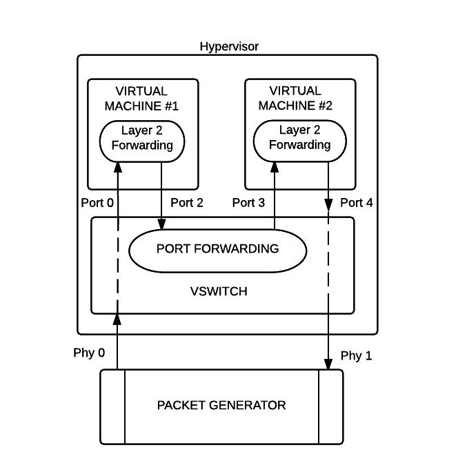
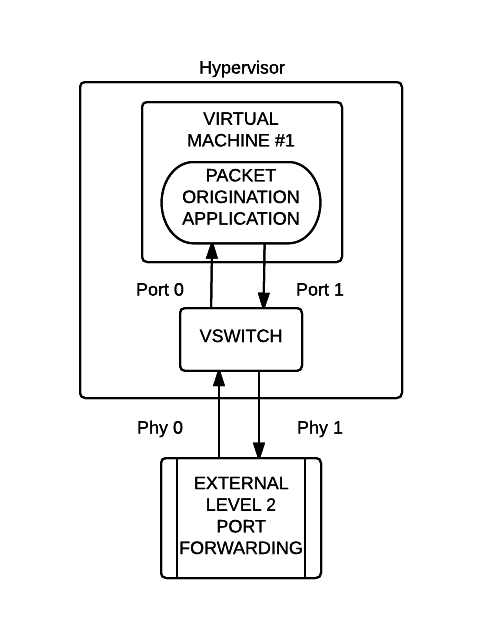
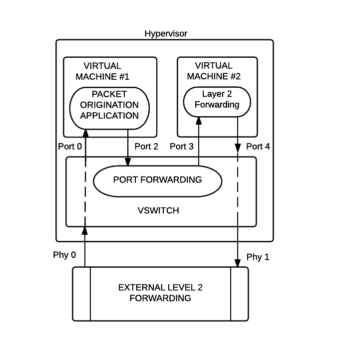
Level 2 forwarding with l2fwd
Many Level 2 forwarding solutions provide only basic forwarding which makes them useful for doing performance and functional testing they are not particularly useful for exercising IP routing and other basic network facilities. While solutions that provide DNAT capability such as iptables often involve significant processing overhead and introduce latency.
An additional complexity is added when virtual machines are in use as many virtual NIC and switch solutions since these may have multiple ports and require an accurate destination IP for internal routing. The l2fwd module addresses this issue by providing simple L2 forwarding with optional address translation for all Ipv4 layer 2 packets. To simplify the implementation non-IP packets such as ARP are passed through for processing by the host IP stack. By default when loaded with no parameters l2fwd will provide forwarding between the ‘eth1’ and ‘eth2’ device without packet forwarding.
So how does it work. Let us consider two hosts, A and B with two ethernet ports connected back to back. Host A is a software packet generator provisioned with 172.20.10.1 ( mac address fe:ed:be:ef:ca:fe ) on eth1 and 172.20.20.1 (ca:fe:ba:be:fe:ed) on eth2 while host B is a loopback device providing Layer 2 forwarding and is provisioned with 172.20.10.2 (mac address de:ad:be:ef:ca:fe) on eth1 and 172.20.20.2 (mac address de:ad:be:ef:fe:ca) on eth2.
Host B is provisioned to provide L2 forwarding with DNAT using this command line:
insmod ./l2fwd.ko net1=eth1,172.20.10.1, fe:ed:be:ef:ca:fe net2=eth2,172.20.20.1,ca:fe:ba:be:fe:ed
With this command line all packets that enter Host B on eth1 will be forwarded to eth2 with DNAT.
To see this working let’s examine what happens to ping packet from Host A to destination IP 172.20.10.2. Initially Host A sends an ARP request to obtain the MAC address for the destination host. When this is received by l2fwd it determines that this not an IP packet and forwards it to the host stack which responds correctly.
Next Host A will send an ping packet (ICMP echo request). Since ICMP packets are IP packets when this packet is received on eth1 on Host B it will get queued for forwarding on eth2. Prior to the transmission by the eth2 driver the destination IP will be translated from 172.20.10.2 ( the original destination ) to 172.20.10.1 ( the DNAT destination ), the destination MAC will be translated from de:ed:be:ef:ca:fe to ca:fe:ba:be:fe:ed, and the source MAC and IP addresses will be translated to the corresponding values for eth2 on Host B.
When the echo request is received on eth2 of Host A it appears to be a normal echo request from eth2 on port B and an ‘echo reply’ is sent. When this is received by eth2 on Host B it is forwarded to eth1. Prior to transmission by the eth1 driver on Host B the destination IP will be translated from 172.20.20.1 ( the DNAT destination for eth2 ) back to 172.20.10.1 ( the dnat destination for eth1 ). This packet is received by the ‘ping’ command and reported on the console which reports the round trip time. As far as ‘ping’ is concerned it send a packet to 172.20.10.2 and got an answer, however using tcpdump on eth2 of Host A shows the echo-request being received eth2 (172.20.20.2) on Host A and a response sent to eth2 on Host B.